![]() a hexagonal-grid based MCAD tool
a hexagonal-grid based MCAD tool
Better control over curve and surface specification
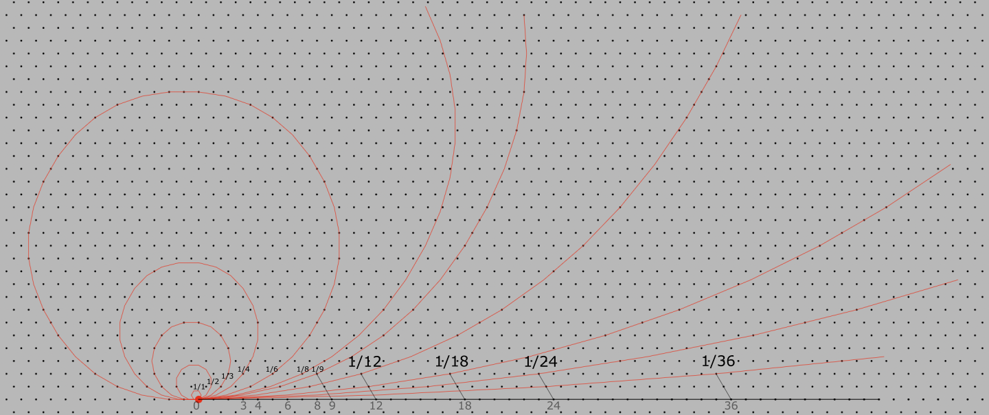
The Specifier uses a hex-grid to specify curves and surfaces. Curvature on a hex-grid can be specified using a single integral ratio. It is possible to step on the grid at a given curvature-step and control the length of the step. This gives a designer better control over curve and surface specification than tools (such as Solidworks) that don't use a grid in the specification process.
Specifier 1.0: differentiating features
In addition to its use of a hex-grid for curve and surface specification,
Specifier 1.0 targets new design and prototyping,
and fits more efficiently into a design-prototyping process than any existing tool.
It is not a full-featured tool (such as Solidworks) meant for a factory or large scale industrial production use.
The Specifier is being designed in sync with the design of a bicycle-trailer prototype. Hence it's design is use-centric and domain specialised, which makes it an efficient addition to a specific design-prototyping process. It provides the ability to specify both a finished design and its construction process unlike tools like Solidworks that do not provide for construction-process specification.
The Specifier uses a simpler UI (called InterUnit-UI) that the commonly used WIMP UI.
InterUnit-UI  , is a new UI-design paradigm that has far better ergonomics than WIMP.
Most existing tools are not that simple to use (they all use WIMP).
Shapr3D is a recent tool that has been specially designed for ease of use.
, is a new UI-design paradigm that has far better ergonomics than WIMP.
Most existing tools are not that simple to use (they all use WIMP).
Shapr3D is a recent tool that has been specially designed for ease of use.
Includes some ergonomic modeling of the user of the design. This is a neccesary part of the specification of any structural-assembly that will be used by a human user.
The Specifier uses a hexagonal grid as an underlying graphic design basis, and implements a specially designed hex-grid graphics library.
This library does not rely on 3D hardware acceleration,
and is implemented, instead, using a platform's native 2D drawing library.
It is also designed with a minimal feature-set and resource usage approach.
These implementation choices signifantly lower The Specifier's computational complexity, and it will be very responsive on average PC hardware as a native app.
(All existing tools have high implementation compleixty and are either implemented as native apps, requiring workstation class processors,
or cloud-based apps, implying browser and internet-bandwidth constraints).
Licensing
Khitchdee Design ( ) plans to license the Specifier to industrial-designers and prototype developers.
We also plan to license the Specifier's hex-grid based geometry modeller to other MCAD tool vendors.
) plans to license the Specifier to industrial-designers and prototype developers.
We also plan to license the Specifier's hex-grid based geometry modeller to other MCAD tool vendors.
Competition: A review of current MCAD tools
Current MCAD tools represent solid objects using parametric descriptions created using a "geometry-modeler".
To visualise these solid objects on a 2D screen, they are represented by their 3D boundary surfaces (BREP).
The ISO has standardised a format for BREPs and all tools support this format for interchange.
For most industrial design projects, a 3D surface does not need to be edited directly.
Common shapes are used and ther properties are controlled using the app.
Sometimes, as in the case of specialised exterior sheet-metal design for an automobile,
specialised tools are used to directly specify 3D surfaces.
In addition head-mounted-displays, which offer a full 3D viewing experience are used for visualisation.
Motion sensing sensors can be used to input shapes using hand movements.
Hand-gesture based 3D surface input is a new direction that tools are starting to explore.
Direct 3D surface design is still a process with a learning curve and its use is not very prevalent.
Clay models continue to be used to create 3D surface designs, such as for automobile design.
From a designer's standpoint, MCAD tools are characterised by their geometry kernel.
Examples of geometry kernels, currently in use, are Parasolid (Siemens), 3D ACIS Modeller (Spatial), ShapeManager (Autodesk), Granite (PTC), Convergence Geometric Modeller (Dassault), openNURBS (Rhino3D) and C3D (C3DLabs).
For new product designs associated with prototyping or small-scale production processes, the following MCAD tools are commonly used.
The most commonly used tool
Solidworks
![]()
Platform: Windows or Cloud
Geometry Kernel: Parasolid
Launch date: 1995
Annual revenues (estimated): $1.5B
Location: MA, USA
Cloud-based collaboration enabled tools for smaller scale industrial-design
PTC OnShape
![]()
Platform: Saas on Cloud
Geometry Kernel: Parasolid
Launch date: 2012
Annual revenues (estimated): $245M
Location: MA, USA
Autodesk Fusion360
![]()
Platform: Windows, MacOS, Cloud
Geometry Kernel: ShapeManager
Launch date: 2013
Annual revenues (estimated): $20M
Location: CA, USA
Established MCAD tools for industrial-design targeting small-scale manufacturing
Alibre
![]()
Platform: Windows only
Geometry Kernel: Parasolid
Launch date: 1997
Annual revenues (estimated): $12.6M
Location: TX, USA
IronCAD
![]()
Platform: Windows only
Geometry Kernel: Parasolid or ACIS
Launch date: 2001
Annual revenues (estimated): $5M
Location: GA, USA
Niche MCAD tools (ease-of-use and NURBS based modeling)
Shapr3D
![]()
(ease of use)
Platform: iPadOS + Pen, AppleVision Pro, Windows, MacOS
Geometry Kernel: Parasolid
Launch date: 2013
Annual revenues (estimated): $14.6M
Location: Hungary
FlyingShapes
![]()
(HMD + hand-gesture based input)
Platform: AppleVision Pro + NVidia CloudXR, Windows based HMDs
Geometry Kernel: C3D by C3DLabs
Launch date: 2025
Annual revenues (estimated): unknown
Location: Germany
Rhino3D
![]()
(NURBS modeling)
Platform: Windows, MacOS
Geometry Kernel: openNURBS
Launch date: 1998
Annual revenues (estimated): $13.1M
Location: WA, USA
MCAD related articles
The domain of MCAD has evolved since the first tools for 3D modeling and visualisation wer introduced about 30 years ago.
Mechanical CAD tools require a mechanism for visualising 3D objects on a 2D display.
We present a brief review of the underlying technology involved and how major MCAD tools use that technology.
We focus on structural design and the design of metal-based structures. Thge link below is a description of our design specification process for a structural-assembly.
A Hexagonal grid is like an extended virtual protractor
(the instrument used to measure angles).
It can be used to choose or specify angles and curves in a mechanical CAD process.
What is design-specification?
There are 2 aspects to the specification of a land-vehicle design.
- A structural specification.
A static description of the built up structure of a design.
It includes a specification of each part in a design,
how the parts connect with each other,
and a structural model of the user (if applicable).
- A construction-process specification.
Specifies the construction-process of a design.
How each component in the design is contructed
and how the components are put together to produce the design.
This is useful for an assembler or a fabricator.
What is specification visualisation?
A (design-specification) Visualiser implements perspective-correct display-screen mapping of modelled 3D objects.
Our visualiser models a camera with a location and orientation,
and a single light source, at the same orientation and location as the camera.
We represent a 3D object as its outer surface,
a lattice of 3D planar segments.
We map these 3D planar segments onto a 2D screen using 4-point plane-mapping.
A curved plane (in 3D) is modelled as a lattice of flat planes.
Our visualiser uses only the device's (2D) drawing engine,
and targets a visualisation time of 100ms/frame
for a bicycle-model at 4K resolution on an Snapdragon 8 Gen 5 SOC class device.
Construction-process specification in the Specifier (planned)
We plan to produce a construction-processes specification component
after the structural specification component.
The designer will identify several construction states in the construction process.
Each construction state will be a physical model of the relative placement of the components and tools in the process.
The designer will indicate transitions between construction states.
The construction-process specifier will use these construction states and transitions between them
to create an interpolated sequence of models to be visualised.
This sequence will be visualised using the Visualiser with some animation controls.
Photograph assisted specification in the Specifier (planned)
After the mouse and keyboard specification interface,
we plan to produce an additional interface to improve structural specification input efficiency.
This interface will work as follows:
- A designer loads photographs of a real object into the app
(with a description of the approximate camera parameters used in taking those photographs). - Identifies (in terms of 2D point descriptions) the components in the structure of the object in the photograph.
- For each component, they describe its 3D orientation and size, based on physical measurements.
Structural overview of a bicycle
A bicycle is specified as a primary frame and components,
attachment mechanisms between them,
and additional braking and gear-ratio control systems.
A. The primary frame and components.
- A frame consisting of:
A head-tube, top-tube, down-tube and seat-tube.
A seat-stay and a chain-stay at the back.
A bottom bracket at the base of the frame.
Connectors that connect the parts in the frame. - The front fork and handle-bar
- The chain-drive consisting of:
a chain crank and pedals
a freewheel
a chain - The front-wheel, front-wheel spindle and tire
- The rear-wheel, rear-wheel spindle and freewheel attachment, and tire.
B. Attachment specifications between the primary frame and components.
C. The braking system and optional gear-ratio control systems.
- A braking system and its attachment mechanism
- A gear-ratio control system and its attachment machanism